Radiography of the skull is difficult because in no other parts of the body are there so many structures that can be identified in radiographs of so small an area.
The minimum number of views that must be obtained to demonstrate all areas of the skull clearly is five. These five views are the posteroanterior, the Caldwell, the Towne, the lateral, and the base. If the sinuses or facial bones are involved, the water's view is essential. The discussion and the illustration of all the six views of the skull are as follows.
 |
| 👻💀💀💀💀👻 |
👻Six views of the skull are as follow:
- Posteroanterior view
- Caldwell view
- Towne view
- Lateral view
- Base view
- Waters view
1. Posteroanterior view
The posteroanterior view of the skull is the best view of the year. otolaryngologist, who live in an audio-centric world, describes this view as the transorbital view because the petrous pyramid and the ear as seen within the orbit of the skull have been demonstrated the ear so well. Therefore, the area that should receive the most attention during the interpretation of a posteroanterior view of the skull is showing the structure of the inner and the middle ear.
2. Caldwell view
It the posteriointerior view can be regard as the "ear view" The caldwell, or inclined posteriointerior view could be considered the primary "orbit view" because it demonstrates the margins of the orbits and the structures that make up the orbital wall better than any other view. caldweel view is also uniquely valuable for demonstrating the mid line structures of the skull and the face.
3. Towne view
If the posteriointerior view is the ear view and the caldwell view is the orbit view, then the towne, or half-axial anterioposterior view could be considered the "occiput view" because it is the only view that can clearly show the occiput and the structures of the posterior carinal fossa. The towne view could also be regarded as an axillary ear view. only on a towne view can the mastoid antrum and the mastoid air cells on one side of the skull be compared with those on the other side on the same radiograph.
4. Lateral view
The lateral view is the only view of the skull that shows the shape and the depth of the sella turcica. When the length and the deapth of the sella turcica measured on the lateral view are combined with the width of these structure determined from the right-angle view its floor on the caldwell view, the volume of the sella turcica can be calculated. The width Of the sella turcica multiplied by one half of the product of length times the depth equals the volume.
5. Base view
The base, or submentovertical, view is uniquely valuable for visualization of the structures in the base of the skull and those structures that are oriented in a more caudocephalad directions.
6. Water's viewIf the posterioanterior view is the ear view and the caldwell view is the orbit view, the water's or inclined posterioanterior view could be considered the "maxillary antrum view" because it shows the maxillary antrum better than any other views of skull. The roof of the maxillary antrum is the floor of the orbit. The water's view, therefore, is also the best view of demonstrating the orbital floor. on the water's view, the floor of the orbit is represented by two lines that are parallel to each other. The superior line is the anterior margin
👻Six Main Position view of skull💀
- Mastoid
- Optic foramen
- Mandible
- Temporomandibular (TM joint)
- Styloid process
- Nasal bone
1. Mastoid
Schüller position or lateral oblique view (film size-6,1/2"×8, 1/2")
Position of the patient
The patient is asked to lie in a prone position. place the head in a true lateral position. The interorbital is at a right angle with the cassette. The auricle of the ear near the film is folded forward (Fig. 1.1).
Central ray
The central ray is directed at an angle of 30 Towards the feat. The central ray enters the skull above the year at the partial region and passes through external acoustic meatus proximal to the film (Fig. 1.2)
2. Optic foramen
Posteroanterior oblique view (film size-6,1/2"×8, 1/2")
Position of the patient
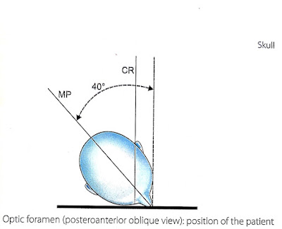
Ask the patient to lie in a prone position with the head of the patient in the nose chin position. Rotate the head 40°, toward the optic canal to be examined until nose, molar bone and chin are touching with the cassette (Fig.1.2).
 |
(Fig. 1.2) Optic foramen ( posteroanterior oblique view) : position of the patient
|
Central Ray:
The central ray is directed vertically with an angle of 20° toward the feet. The rays enter the head from opposite occipital region and pass through the orbit near the cassette (Fig. 1.3)
 |
(Fig. 1.4) Optic foramen (oblique view): line drawing of the radiograph. 1- optic foramen; 2- supraorbital ridge; 3- frontal bone; 4- sphenoid ridge; 5- sphenoid air sinus; 6- sella turcica; 7- frontal process of zygomatic bone; 8- zygomatic arch
|
Exposure settings
Distance - 100
Focal spot - Large
Grid - yes
mA station - 100 or 200
Exposure factors - kV - 75 (60-65)
mAs- 120-160 (60-80)
3. Mandible
Posteroanterior view (film size- 8"×10" Or 10"×12")
Position of the patient
The patient is asked to lie in a prone position. The head in the posteroanterior position with the radiographic baseline is a right angle (90°) to the film. (Fig.1.5)
Central Ray:
The central ray is directed vertically entering the nap of neck and passing through lips. The patient is instructed to stop breathing during the exposure.(Fig. 1.6)
Exposure settings
Distance - 100
Focal spot - Large
Grid - Yes
mA station - 100 or 200
Exposure factor. - kV - 65-60
mAs - 120 48-60
Lateral Oblique view (film size- 8"x10")
Position of the patient
Patient is asked to lie in lateral recumbent position with body of mandible (the side with is to be exposed) resting on an inclined plain of 17 . The chin is extended and head is thrown back to minimise the over shadowing effect of cervical spine. The body of mandible (near the film) should be parallel to the upper edge of cassette.(Fig. 1.7)
Central Ray
It is directed vertically with an angle of 10 towards head passing through lower last molar tooth. the patient is asked to stop breathing during exposure.(Fig. 1.8)
Exposure settings
Distance - 100
Focal spot - Large
Grid - No
mA station - 200
Exposure factors - kV - 50 55
mAs - 12 16
4. TM joint (Temporomandibular)
Lateral View (open and closed) (film size- 8"x10")
Position of the patient
Patient is asked to lie in prone position with head in true lateral position. Median plane of head is paralled to the table top and external auditory meatus is centred in the midline of table and cassette. The opposite side hand is cluched and place under the chin as a support (Figs 1.14A to D)
Central ray
the central ray is directed vertically with the angle of 25 degree towards feet passing through the external auditory meatus of the side t be radiographed (Fig. 1.15).
Exposure settings
Distance - 100
Focal spot - Large
Grid - Yes
mA station - 100 or 200
Exposure factors - kV - 60 65
mAs - 100 48-60
Orbit View
The patient is supine (or sitting erect), and the head is placed in the anteroposterior position with the base line at right angles to the table (Fig. ). The head is moved away from the side under examination so that the central ray is angled 10 towards the feet and passes through the centre of orbit. The head is then rotated 5 towards the effected side in the sagittal place. E act joint is taken separately, with the mouth closed. It should be noted that injury radiographs of normal subject(Fig. ), appearances are similar with the mouth closed and with the jaws thrust forward. However, their relationships may be maintained when there is an abdominal conditions of the joint.
Anteroposterior view
The joint will also be shown simultaneously by using the modification of the 30 occipitofrontal projection.
Again the position is best taken with the mouth open. Center above glabella, with the tube angled at 30 to baseline to a point midway between the temporomandibular joints.
Posterior position (superoinferior)
The patient is prone or sitted erect, the chin is placed firmly on the table and the neck is hyperextending. The base lined is angled at 40 with the table. centre through the temporomandibular joints angling the tube 15 towards the feet. This view is best taken with the mouth closed(Fig. ).
5. Styloid process
Anteroposterior view (film size- 10"x12").
Position of the patient
Ask the patient ti lie in the prone position. The skull is positioned in true anteroposterior position. Median plane is perpendicular to the cassette and in the centre lie of the film. Ask the patient to ope mouth and 2 1/2" size cork between the teeth. Now the head is adjusted in the position that line Dra from the root of nose to external meatus should be perpendicular to the film (Fig. )
Central ray
The central ray is directed vertically with an angle of 15 towards feet. rays passes through inferior margin of orbit and external acoustic meatus.
Exposure settings
Distance - 100
Focal spot - Large
Grid - Yes
mA station - 100 or 200
Exposure factors - kV - 75 65-70
mAs - 160 60-80
6. Nasal Bone
Lateral view (film size- 6 1/2"x8 1/2")
Position of the patient
patient is asked to lie in the prone position. The head is positioned in true lateral position. Put the film on a small bag, so that the film is near the nasal bone (Fig. ).
Central ray
The central ray is directed vertically passing through the distal end of nasal bone (Fig. ).
Exposure settings
Distance - 100
Focal spot - Large
Grid - no
mA station - 100
Exposure factors - kV - 46
mAs - 4-6
Skull💀💀- Diagrammatic Radiographic Analysis Of Six Views Of Skull💀💀!👆👆


Post a Comment